





Mittelstandspresse
02.11.2026
Thermal Time of Flight: Precise Flow Measurement for Demanding Applications
Glattbrugg, 02.11.2026 (PresseBox) - .
1. Limits of Classical Thermal Measuring Principles
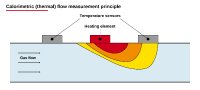
Thermal flow measurement is one of the most successful measuring principles in flow metrology. Since the first commercial implementation of a flow sensor based on the calorimetric principle, adoption has grown to more than 25 million flow sensor chips (MEMS) shipped every year, with the thermal measuring principle dominating. In medical technology, process automation and analytics, thermal sensing is well established (Silvestri & Schena, 2012). Two methods define this field: calorimetry and anemometry. Both methods are based on evaluating steady-state heat transport. In the calorimetric principle, a heating element is placed between two symmetrically arranged temperature sensors. The flow shifts the temperature profile, and the difference between the upstream and downstream sensors is a measure of the mass flow. In anemometry (Constant Temperature Anemometry, CTA), a heated element is kept at a constant temperature: the heating current required to maintain the temperature difference is the measured quantity (Angst+Pfister Sensors and Power AG [APSP], n.d.-a; Kuo et al., 2012).
However, these methods reach their limits as soon as small and strongly varying flow rates must be measured precisely. Calorimetric sensors deliver a flat, noisy signal at very low flows and saturate at high velocities. The maximum measurable flow velocity of commercially available calorimetric sensors is typically below 15 m/s (APSP, n.d.-a). Above all, however, the signal depends on the thermal properties of the medium: if the gas composition changes, the sensor must be recalibrated. The reason lies in the measured quantity itself: the calorimetric reading depends on the specific heat capacity of the gas and on heat conduction losses into the packaging (end conduction loss), so the best accuracy requires calibration with the actual gas (ISO 14511). In production, this is often impractical because process gases are expensive or cannot be used for safety reasons; an air calibration with a theoretical conversion factor, on the other hand, introduces errors that cannot be precisely controlled, as well as additional nonlinearity across the dynamic range. For applications that combine different media, a wide required dynamic range and low minimum flows, this is a structural disadvantage.
2. Measuring Principle: Thermal Time of Flight (TTOF)
The TTOF method does not measure steady-state heat dissipation but the transit time of a heat front. A heating element generates a short thermal pulse. This pulse is carried along by the flow and reaches a downstream sensing element after a measurable time. If the distance between heater and sensor is L and the transit time of the heat front is t, the flow velocity follows directly from V = L/t (Figure 2). In real applications, heat diffusion in the medium is superimposed on the convective propagation of the heat pulse. The evaluation therefore corrects the measured transit time for the diffusion component, which is obtained by solving the heat transport equation; only this correction makes the measurement largely independent of the heat conduction losses of the assembly.
The key difference from calorimetry, which relies purely on heat dissipation, lies in the quantity being evaluated. Calorimetry measures an amplitude, namely the temperature difference, and this amplitude depends directly on the thermal conductivity and heat capacity of the medium. The TTOF method, by contrast, measures a time in the transient signal. Time-based signals are considerably more robust to background interference than amplitude-based ones. That the calorimetric and transit time principles can be combined on one chip, and that the transit time mode significantly extends the usable measuring range,was demonstrated experimentally as early as the late 1990s (Ashauer et al., 1999). Angst+Pfister follows exactly this approach with the PFLOW series: the sensors implement the TTOF principle in combination with calorimetric evaluation on a single MEMS chip, combining the extended measuring range of the transit time method with the sensitivity of calorimetry at low flows.
In the micromachined design, the heater is combined not with one but with at least two downstream sensing elements whose distances (x1 and x2) are precisely defined by the photomask (Figure 3). The elements sit on a thin, thermally insulating membrane above an etched silicon cavity. From the two transit times, both the thermal diffusivity of the fluid and a flow velocity independent of the fluid properties can be calculated. Unlike calorimetry and anemometry, TTOF thus delivers more than just the flow rate: it enables a multi-parameter measurement that also allows conclusions to be drawn about the properties of the medium.
3. Technical Advantages of TTOF
Compared with amplitude-based methods, TTOF offers four structural advantages:
Wide dynamic range: The turndown ratio indicates the factor by which the largest measurable flow exceeds the smallest flow that can still be measured within the specified accuracy. The literature reports dynamic ranges of up to 1400:1 for micromachined TTOF structures; in practice, modern MEMS flow sensors achieve turndown ratios of up to 500:1. Manufacturer data for methane show how strongly the measuring principle matters here: if an air-calibrated calorimetric sensor is mathematically converted to methane, around 30 percent of the dynamic range is lost; with time-based evaluation, this loss does not occur because the thermal diffusivities of air and methane differ only slightly (APSP, n.d.-a).
Self-calibration potential: Since time and a geometrically defined distance are evaluated directly, a simple calibration with a readily available fluid (such as air or water) can be sufficient to measure other media without loss of accuracy. The decisive factor is thermal diffusivity: gases with the same thermal diffusivity, such as air, oxygen, nitrogen and argon, deliver almost identical readings and can therefore all be calibrated with air, which simplifies argon applications such as welding process control.
Media independence and biocompatibility: TTOF addresses the media dependence where calorimetry and anemometry fall short; at the same time, the low heat input (a temperature rise of around 5 K) protects temperature-sensitive drugs and biological samples (Doh et al., 2022). Manufacturer data from anesthesia show how large the benefit in gas conversion is: when an air calibration is converted to nitrous oxide (N2O), the conversion factor of the time-based evaluation remains linear over the entire measuring range (R² = 1.000), whereas the calorimetric evaluation shows pronounced nonlinearity (R² = 0.997).
Low thermal drift: Because a transit time rather than an absolute amplitude is measured, the method is insensitive to baseline shifts; thermopiles and good thermal insulation further reduce drift.
4. Use Cases
Three practical applications show how the principles described work in real systems, and how much the role of the sensor can vary.
Process gas control in semiconductor coating. In sputtering and PVD systems for thinfilm deposition, layer thickness, uniformity and reproducibility depend directly on precise dosing of the process gases, such as argon as the sputtering gas or reactive gases such as oxygen and nitrogen. The control loop operates at the interface with the vacuum process, must handle fast transitions between process steps and must remain repeatable over long production campaigns; when the process switches gases, measurement accuracy must be maintained. The PFLOWC5002 mass flow controller combines a thermal MEMS sensing element with an integrated control valve and is factory-calibrated for two process gases, with switching between the calibration curves handled in software by the system controller (APSP, n.d.-b).
CO2 insufflation in endoscopy. In minimally invasive surgery, insufflators use CO2 to create a defined working space inside the body, such as the pneumoperitoneum in laparoscopy. The flow sensor provides the feedback variable for closed-loop pressure and flow control: it measures the CO2 flow actually delivered, from which the device tracks the volume balance and keeps the intra-abdominal pressure within the therapeutic window. The measuring task demands both ends of the measuring range at once: very fine flows for pressure-controlled readjustment and pediatric use, and high flow rates of several tens of liters per minute when leaks or smoke evacuation must be compensated for. In addition, pulsating delivery profiles require a fast response time. The PFLOW9015CL is used successfully for this task (APSP, n.d.-b).
Pneumatic integrity monitoring in genomic analysis. In instruments for single-cell analysis and sample preparation for next-generation sequencing, samples and reagents are partitioned and processed in microfluidic cartridges (Lin et al., 2022). They are moved not by pumps in the liquid path but pneumatically by controlled gas pressure. The reliability of this pneumatic path therefore directly determines the quality of the analysis result, because a blocked line leads to a silent failure that, without dedicated monitoring, would only become apparent from the faulty result. Here the flow sensor serves not a dosing function but a diagnostic one: it continuously verifies that gas is flowing at all, and at the expected order of magnitude.
A customer-specific variant of the PFLOW2001 with a full scale of 30 sccm, gascalibrated and with a digital I2C interface, is used (APSP, n.d.-c). What matters here is not accuracy at the nominal operating point but reliable resolution of very small flows and unambiguous signal behavior at the lower range limit.
5. Challenges
Why, then, has TTOF not displaced the established methods? In discrete designs, evaluating a transient transit time signal required considerably more circuitry than the simple amplitude measurement of calorimetric sensors. This complexity was historically a key reason for its lower adoption. In modern MEMS sensors, however, this evaluation has moved into the integrated electronics, so the additional effort at component level no longer represents a cost disadvantage in practice; at system level, the equation is even reversed, because simplified calibration eliminates expensive actual-gas calibrations and additional sensor variants. There are also physical limits at both ends of the measuring range: at the upper end, very fine time resolution is required; at the lower end, the signal becomes blurred. Depending on the design, power consumption is also higher than with calorimetry, but it can be reduced to a few milliwatts through pulsed operation.
The lower range limit is not a matter of electronics but of physics. Below the specified turndown ratio, accuracy does not decrease gradually; rather, the useful signal is lost in effects that have nothing to do with the flow. In TTOF, heat diffusion dominates the transit time as soon as the flow velocity becomes small compared with the propagation velocity of heat in the medium: the pulse then reaches the sensing element even without flow, and the measured time becomes increasingly independent of the flow. In amplitude-based methods, the same mechanism acts through free convection. For a thermal sensor with thermopile readout, the practically achievable detection limit was determined to be 0.8 mm/s, while the pure noise limit is 0.13 mm/s; the difference is essentially due to natural convection, which was identified as the main obstacle to measuring very small flows (Issa & Lang, 2013). In addition, there is the zero offset of the signal chain, which mimics a flow where there is none and whose drift accumulates without bound when integrated to a volume (Piotto et al., 2017).
In practical terms: below a certain flow rate, a thermal sensor can no longer reliably distinguish whether the medium is flowing very slowly or not at all. Where precisely this distinction is the actual measuring task, for example when verifying that a line is not blocked or when detecting an idle state, the design criterion is therefore not accuracy at the nominal operating point but signal behavior at the lower range limit.
The design thus remains a compromise: a greater distance between heater and sensor provides a stronger transit time signal, but requires more power and reduces the usable dynamic range.
6. Conclusion and Outlook
The difference between the thermal measuring principles can be traced back to a single point: calorimetry and anemometry evaluate an amplitude, whereas Thermal Time of Flight evaluates a time. Because a transit time is measured over a geometrically defined distance, the result depends far less on the material properties of the medium and is less sensitive to drift and background interference; moreover, flow velocity and fluid properties can be determined separately from two sensor distances. What the change of principle does not eliminate is the lower range limit: it follows from the physics of heat propagation and from the zero offset of the signal chain, and it applies equally to time-based and amplitude-based methods (Issa & Lang, 2013; Piotto et al., 2017). The choice of measuring principle is a system decision: whether the ability to switch gases, the dynamic range or an unambiguous signal at the lower range limit takes priority is decided by the application, not by the technology. Calorimetry remains by far the most widespread method, and the design of a TTOF sensor remains a trade-off between signal strength, power consumption and dynamic range. The hurdle that long held TTOF back, however, has been overcome: with the integration of signal processing into the sensor electronics, the once-high circuit complexity has become a one-time development effort that is amortized over production volume.
At the same time, expectations of flow sensors are shifting: they are expected to recognize which medium they are handling and to report when something is wrong. For this step from transducer to information source within the system, the time-based method is better positioned. Angst+Pfister follows exactly this system logic: depending on the requirements, the PFLOW products use either the calorimetric or the TTOF principle, and where the measuring task demands it, both methods are combined on the same MEMS chip. In this way, the sensitivity of calorimetry at low flows and the wide dynamic range and media independence of the transit time method complement each other, delivering a result that neither principle can achieve alone.
Author: Marius Lamm has been with Angst+Pfister Sensors and Power AG since 2026.
Ansprechpartner
Yun Xu
+41 (44) 877 35 26
+41 (44) 8773525
Zuständigkeitsbereich: Marketing Manager
Datei-Anlagen:

(473 kB)
1637672.attachment
Figure 1: Thermal flow measuring principle. From Theory of flow sensors, by Angst+Pfister Sensors and Power AG, n.d. (https://sensorsandpower.angst-pfister.com/de/produkte/durchflusssensoren-fuellstandssensoren/theoriedurchflusssensoren/)

(551 kB)
1637673.attachment
Figure 2: Schematic of the TTOF principle (top view). A heat pulse is detected downstream by two sensing elements (S1, S2); the flow velocity is derived from the transit time difference.

(479 kB)
1637675.attachment
Figure 3: Cross-section of the micromachined sensing element: heater and two sensing elements (S1, S2) on a thermally insulating membrane above an etched silicon cavity.
- Mehr Infos zu dieser Meldung unter www.pressebox.de
- zurück zur Übersicht